WELCOME!


It is hard to believe that it was only seven years ago I witnessed a CNC router in action for the very first time. I was fascinated and simply had to have one! Although I had been in the creative end of the three dimensional sign business for most of my life I didn't really know what I would do with one - but I just knew it could do fantastic stuff.

Through extensive research I quickly found out that with the relative simplicity of EnRoute, CNC routers were capable of just about anything imaginable. This journal will chronicle that journey to date and continue each week with two or three entries as we continue to explore just what is possible with this wonderful software... -dan

Thursday, January 10, 2013

Building a train - part one


Today I began work on the train. I like to start with the wheels, then the trucks and then work my way up from the frame. I printed out the drawing and then scaled it off to determine the size of the wheels.


It took me half a day to create the vector drawings in scale for all the pieces. It was done entirely in EnRoute.


Because it is a geared locomotive four of the train wheels have gears attached to the face. I started by creating the back flange of the wheel at 0.4" thick. I then selected the next inner circle, this becoming the face of the wheel. It was raised 2.4"


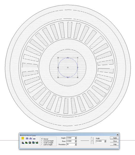
I then raised the teeth of the gears as a flat relief. I used the circle vector around the teeth relief to modify then using the bevel tool. this angled them upwards in the middle. Then I went to the front view and nudged them up into position vertically.


Then I merged highest to the original wheel relief.


The center of the wheel was made by making a relief 3" tall. This was then merged highest with the wheel relief.


To drill the axel hole I created a zero height relief 2" across. This would be merged lowest to the wheel, effectively creating a hole in each wheel.


That created the first type of wheel for the locomotive.
Tomorrow I'll show how we built the second style of wheel.

-dan