WELCOME!


It is hard to believe that it was only seven years ago I witnessed a CNC router in action for the very first time. I was fascinated and simply had to have one! Although I had been in the creative end of the three dimensional sign business for most of my life I didn't really know what I would do with one - but I just knew it could do fantastic stuff.

Through extensive research I quickly found out that with the relative simplicity of EnRoute, CNC routers were capable of just about anything imaginable. This journal will chronicle that journey to date and continue each week with two or three entries as we continue to explore just what is possible with this wonderful software... -dan

Monday, March 31, 2014

How to build a Pelton water wheel.

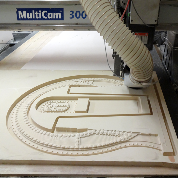
The Pelton water whee isn't a project we routed, nor was it made of Precision board but I thought the readers of this bog might like to see how such a project goes together. The same engineering and figuring that go into this piece apply to many of our other (sometimes) complex projects.
We had all of the pieces for the Pelton water wheel ready to go but no instructions how to put them together. But that was OK because I seldom read the instructions anyway. We would fly by the seat of our pants - as per usual. The key was to think things through and then do everything in the right order and check the measurements often.
We had welded the eight pieces of the rim last week so the first step was to lift the rim of the water wheel into place. The zoom boom took the sweat out of that task. We leaned it up against the wall for when we would need it.

Then we set the pre-assembled hub into place, carefully aligning it with the wall.
Then came the tricky part. We measured the diameter of the inside of the wheel rim, subtracted the distance of the hub and divided the leftover by two. We cut the spokes to that length. I had designed the hub and wheel rim with notches cut into them so we could weld the spokes accurately in the right places without any figuring. Four pairs of spokes were welded in place, measuring from the wall at the rim to get everything relatively true. It worked. Jack was doing the bulk of the welding and I was kept busy figuring out our next move.
Then we welded the inbetween spokes in place working back and forth across the wheel as we went to keep things in balance. Every once in a while we would give the wheel a spin to make sure things were working out as planned. TJ was kept busy cutting the spokes while I measured and Jack welded. It took a couple of hours to get all the spokes fit into place. Once everything was secure it was time to wrap the rim around the wheel and weld it into place. It sounds easy but the rim steel was five and a half inches wide by three sixteenths inch thick and was very heavy. We decided that the best way was to slide one end of the flat bar under the wheel and then weld it securely in place. The wheel was then turned a few degrees and it was welded once more. We slowly worked ourway around the wheel in this fashion, welding on more lengths of flat bar as we went. We ran out of work day before we were done but it is looking pretty good!
We have about six feet of rim to bend around the wheel and weld into place. The paddles also still have to be formed and welded into place. We should be able to wrap things up on the project by noon. Now we know how a Pelton water wheel goes together should we ever have to do one again.
-dan

Saturday, March 29, 2014

Handy uses for the EnRoute program

EnRoute is a powerful routing program without a doubt. I can create some pretty cool routing files using it but it is also handy for so much more. When I need to create a plan view of something to scale it is the CAD program I turn to.

Last week I used it to design the plasma cutting files for a Pelton water wheel that we are building for our current theme park project. As always I designed the concept art in Photoshop. This artwork provided the ideas to then create the cutting files in EnRoute.

I neglected to capture the creation process but it was pretty easy. The wheel rim is twelve feet six inches in diameter and six inches wide. There are 32 spokes which were arranged at the appropriate angle. I then used the jigsaw tool to cut the notches into the rim and hub of the wheel pieces. Then I created the division lines to cut the wheel rim into eight pieces so it would fit on a four by eight sheet of 1/4 steel and used the jigsaw tool to create each segment. I created the join plates, paddles and hub center rings and then arranged them onto two four foot by eight foot plates. These were exported as DWG files for my steel worker friend with the cnc plasma cutter.


The pieces were cut perfectly. Today we welded the center section together in the shop. The rest of the fabrication will happen on site as the piece is too big to move once it is assembled.


Another very large project I used EnRoute on is the plan for a project we are next taking on. It is for a two and a half acre theme park in Trinidad. My job at this point was to draw up the concept plans for the park. They need to be in scale but also need to appear hand drawn. Others will later draw up the building plans using a CAD program.

I was sent the plot plan as a PDF. I opened this and then did a screen capture which I then saved as a JPG file. This I imported into EnRoute and then traced using the drawing tools. I was able to establish scale from known measurements and so I resized the drawing to this scale. I could then add new elements accurately. Building sizes and railroad turning radii were important to establish and determined how everything was placed and fit together. Once I had all of the basic information in place I first saved it for future reference and then again created a screen capture. 


This screen capture was then opened in Photoshop so I could redraw the image once more with the appropriate detail and color needed for the presentation art needed for the concept art of the park. The planners and engineers will use this reference material to generate the final plans for the park.


EnRoute is indeed a powerful program useful for far more than its creators imagined.

-dan

Wednesday, March 26, 2014

Pedal Power - Part four

Once the routing was done I glued and clamped all of the layers together using PB Bond 240 glue from Coastal Enterprises. It tends to squeeze out a little on the edges of the seams but that was no problem. I like to use an air powered die grinder to take off the glue and add a little random texture while I'm at it. I also roughed up the faces just a little around the letters. I wanted this sign to look like it has been there a while and has a little character.


Once the cleanup was done it was time for a little welding. I bent up some 5/8" steel rod for the pedals and dug up a pulley from the parts bin. Some pencil rod was bent and welded to form the armature for the bear sculpture.


The sign is now ready for some fun sculpting. Stay tuned...

-dan

Friday, March 21, 2014

Pedal Power - Part three

The pedal power sign is a good size and since I routed it with a 1/8" ball nose bit with an 80% overlap the two sides took about eight hours each to do. The pieces were cut from 1.5" thick 30 lb Precision Board. They turned out great! Tomorrow I'll cut the three half inch thick inner layers and then we'll be ready to start the final assembly.


Stay tuned for more...

-dan

Tuesday, March 18, 2014

Pedal Power - part 2

Building the cut files for the Pedal Power sign was easy and quick once the vector files were complete. The sign faces were only three steps.  First I created a flat relief.


I then modified this relief by using the dome tool.


The letters and rivets were created as a last step - using the same dome tool (with slightly tweaked settings) once more.


The sign is to be built in five layers. The front and back (cut from 2" thick 30 lb Precision Board. The three middle layers would be cut from 1/2" thick Precision Board. The gears would then be cut separate which would allow all of the gears to read as separate and look more believable. The square lines are for a cutout, into which I will insert a welded step frame.


I'll be routing the sign tomorrow and then I'll post the assembly pictures in the next couple of days. 
Stay tuned...

-dan

Monday, March 17, 2014

More awards

We are pleased that two of our last year's projects have been honoured in the Signs of the Times annual international sign competition. Each year they receive many hundreds of entries which compete in various categories.

The Institute for the Study of Mechanical Marine life piece (documented here on the blog and completed last September) won first place in the Unusual Signs category. This sign was designed using EnRoute software. It was machined on our MutliCam 3000 router from 30 lb Precision Board HDU. All finishes were hand brushed acrylic.


The WhistlePunk Hollow Adventure Golf project also garnered a second place finish in the same competition in the SIGN SYSTEM Category. This project was also documented extensively on this blog and was completed last July.

These signs and features were designed using EnRoute software. They were machined on our MutliCam 3000 router from 30 lb Precision Board HDU. All finishes were hand brushed acrylic.


Sunday, March 16, 2014

Pedal Power - Part one

The next critter sign is for a peddle buggy business which is a part of the park. I drew up the concept which the owner approved. It was decided to make the sign two sided which means the gear in the skeleton clock need to look good from both sides and the bear will be rotated 90 degrees. The concept sketch was all I needed to go on.


The lettering and basic shape of the sign was done in Illustrator. I then imported the ai file into EnRoute.


Using the drawing tools I created the basic fancy frame to support the gears. I also added the borders and rivets around the outside.


Creating the gears was pretty simple. I first drew a circle, then a rectangle. A second box was drawn as a measuring device for the next step. I centred all of the pieces with each other.


I then used the point edit tool to bend out the sides of the longer rectangle using the smaller box as a guide. There are more accurate ways of doing this procedure but this was plenty good.


 I then used the array tool to space out the pieces at the right angles.

 And finally I combined the vector shapes to create a gear outline.

 The inside spokes used some of the same methods. Creating multiple copies using the array tool I used a value of 180 degrees. This created one extra copy of the rectangle but rather than do the math  tp calculate the angle I needed to start and finish it was simpler to just delete the extra rectangle and then centre all the pieces in relation to each other.


I used the combine tool with another circle (not shown) to create the spokes of the gear.


The smaller gear used similar functions with similar results.


I then positioned the gears and built new mounting points for them - all work done by eyeball.


These shapes were combined to approximate the result I wanted.

To make the routing and assembly easier I joined the small and large gears using a small rectangle before merging the pieces.


Once I had all of the primary vectors built it was time to decide how many layers the clock would take to convincingly build. I decided five would do it. I then separated, duplicated as necessary and then combined the components in each layer to form the vectors I needed to create the routing files. Here's a screen shot of each layer's vectors. I still have to add the vectors to route out the space for the metal frame in the middle sections.


Next time I'll be showing how we create the reliefs and then in subsequent posts I'll show how we assemble and finish this sign. Stay tuned...

-dan